LPSE v3 Two steps forward, one step back.
I spent more time working on the 3D printable liquid piston Stirling engine tonight and implemented several improvements. The model self-destructed, but I still learned some things.
What worked well?
Sealant elimination:
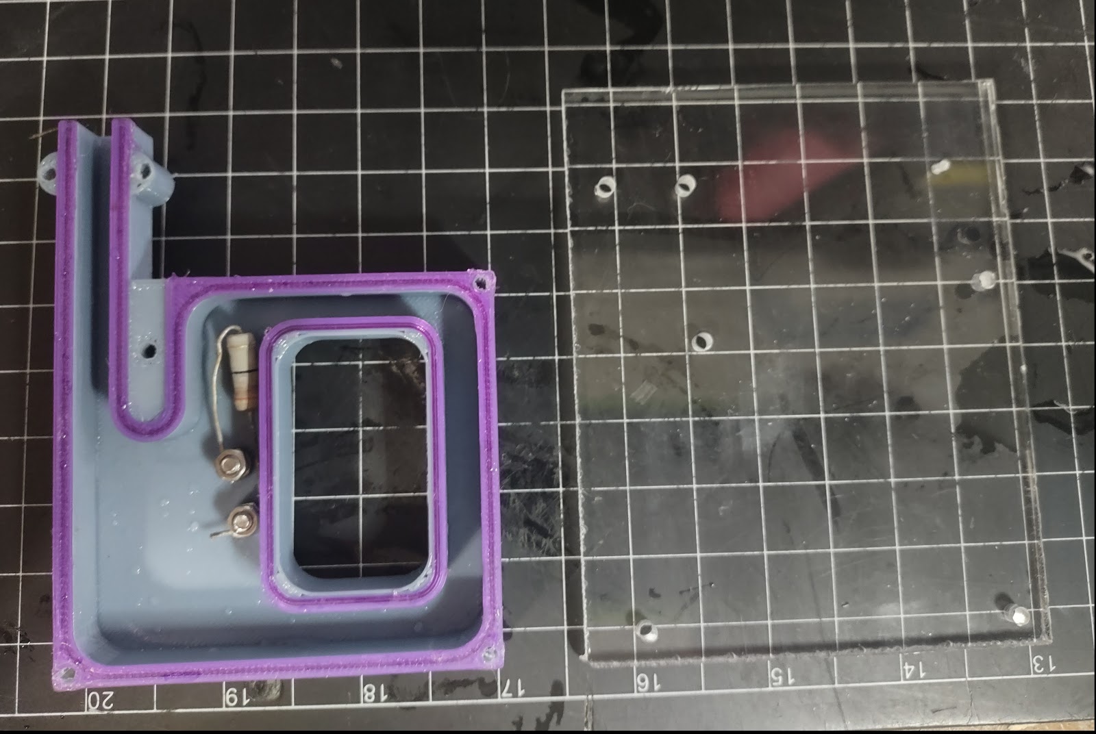
Using a formed TPU gasket of sealant looks promising. The gasket, in purple, is printed in SainSmart TPU. It is a separate component, not a multi-material print. The filament fed well through my MMU so I may attempt a Multi-material print with it in the future.
I threaded two stainless steel M3 fasteners into the liquid chamber as electrical feedthroughs. This worked very well. The resistor/heater leads are held in place with a second nut on the same fastener. As a side effect, this stopped the resistor from flopping around under the pressure of the test leads.
What didn't work?
The holes printed significantly undersize. This is probably a modeling error. Also, there isn't enough material around the holes for screwing on the cover. I could see the housing distort when I drilled and tapped these holes.
To fabricate the cover I created a 1:1 drawing in fusion 360, glued it to the acrylic, cut it out, and drilled the holes. Something in this process went wrong and the print was about 5% undersize. With the holes out of place I wasn't able to use enough fasteners to retain the cover properly. Even reinforced with binder clips. This allowed the working fluid to leak out.
When the water level leaked below the resistor/heater, it self-destructed the housing. The PETG behind the resistor melted, bubbled, and the housing failed.
What can be improved?
The gasket is currently shaped like a T with the bottom leg keying into a slot in the housing. My intuition is that the sealing force is a product of the deformation of the gasket, and the amount of deformation is controlled by the squishiness of the TPU times the compression imparted by the fasteners divided by the surface area of the gasket. I should be able to increase the sealing for the same clamping force by making the contact area between the cover and gasket smaller. That entails making the gasket plus or cross + shaped, so I'll have to do some design work to make that printable. Even a simple rectangle shape might do the trick.
Add more "meat" around the housing.
Drilling and tapping the cover mounting screws in the housing is unnecessary. Just make the holes bigger and use nuts on them.
Add fastener(s) inside the "window" to increase clamping force.
I also spent some time thinking about instrumenting this. I have a sketch to measure voltage and current with an Arduino. I'd like to be able to measure temperature above the heater (the "hot end) and on the other column (the cold end) so I can tell if the currently-not-implemented regenerator is doing anything. I also figured out a possible log the cycle rate. A flap or bobber with an attached magnet can trigger a hall sensor.
I haven't figured out how to implement a displacer in this design.
I haven't figured out how to gracefully adjust the liquid level and the air level in the loop. I think a couple of syringes are a good approach here, but I have to figure out how to seal them into the housing.
That's it. Prototype #3 goes in the "How not to do a thing" drawer.


Comments